How Alloy Choice Changes Die Life and Surface Finish in Extrusion
The alloy selected for an extrusion run determines far more than mechanical strength. Softer, more extrudable alloys such as 6063 flow through the die at lower pressure, which reduces wear on the tooling and allows tighter dimensional tolerances to be held over longer production runs. Harder alloys such as 6061 or 2011 require higher billet temperatures and extrusion pressure, which accelerates die wear and can introduce surface streaking if the die land is not properly maintained between runs. For profiles with visible surfaces, such as those used in lighting housings or architectural trim, this tradeoff between alloy strength and surface quality needs to be decided before die design begins, not after the first sample run reveals a finish problem.
Die correction is another factor tied directly to alloy behavior. Because aluminum springs back slightly after leaving the die, the die opening must be cut with an offset that compensates for this recovery. That offset differs by alloy and by wall thickness, which is why a die designed for one alloy cannot simply be reused for another without remachining the bearing surfaces. Reputable extrusion suppliers keep die correction records by alloy and profile family, which shortens the sampling cycle considerably when a customer later requests the same shape in a different material.
Wall Thickness Limits That Actually Drive Extrusion Feasibility
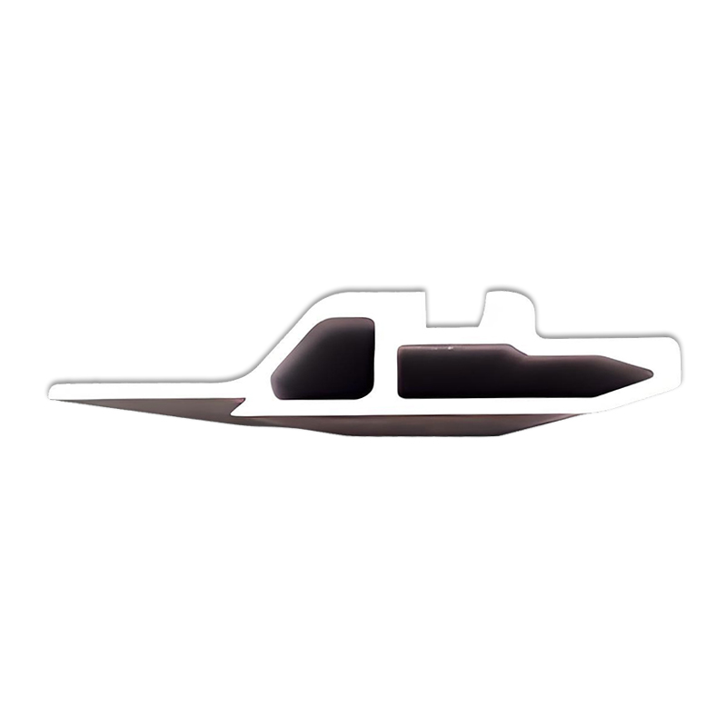
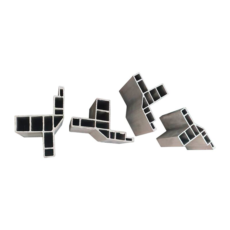
Extrusion feasibility is rarely limited by the overall profile size; it is limited by the ratio between the thinnest wall in the design and the distance that wall spans unsupported. A wall that is too thin relative to its span will buckle or fail to fill completely as the metal cools inside the die, especially in hollow or semi-hollow profiles where internal webs need to hold their shape while still molten aluminum is pushing outward. As a general guide for 6000-series alloys, minimum wall thickness typically falls in a narrow band that depends on the circumscribing circle diameter of the profile, not on the wall's absolute length.
- Solid profiles can generally support thinner walls than hollow profiles of the same circumscribing circle size, since there is no internal cavity to fill under pressure.
- Sharp internal corners concentrate stress during cooling and are a common site for hairline cracking; a small fillet radius at internal transitions reduces this risk without changing the external profile shape.
- Asymmetric wall thickness across a profile causes uneven cooling rates, which can lead to warping after the profile leaves the stretcher; balancing wall mass around the profile's centerline reduces this tendency.
Alloy Comparison for Extruded and Machined Aluminum Components
Selecting between common structural alloys often comes down to balancing machinability, strength, and corrosion resistance against the operating environment of the finished part. The table below summarizes practical differences that matter when specifying a profile or a machined component rather than just picking an alloy by habit.
| Alloy |
Typical Use |
Machinability |
Corrosion Resistance |
| 6063 |
Architectural and lighting profiles |
Good |
Excellent |
| 6061 |
Structural brackets, heat sinks, machined housings |
Good |
Good |
| 7075 |
High-stress aerospace and precision components |
Moderate |
Fair, often requires coating |
| 2011 |
High-speed CNC turned parts |
Excellent |
Poor without treatment |
Tolerance Classes Worth Specifying on a Machining Drawing
Many delays in custom machining projects trace back to a drawing that specifies a single blanket tolerance for every dimension instead of applying tighter tolerances only where they are functionally necessary. Bearing bores, mating surfaces for gaskets, and press-fit diameters usually need tolerances in the range of ±0.02 mm to ±0.05 mm, while non-mating dimensions such as overall length or non-functional edges can often be held to ±0.1 mm or looser without affecting assembly or performance. Specifying tight tolerances everywhere increases cycle time, tool wear, and inspection cost without adding functional value.
GD&T Callouts That Reduce Rework
Geometric dimensioning and tolerancing callouts such as flatness, perpendicularity, and true position are more informative to a machinist than a string of linear dimensions alone, because they describe the functional requirement rather than forcing the shop to infer it. A part that mounts against another component benefits from a flatness callout on the mating face; a part with multiple mounting holes benefits from a position tolerance with a datum reference frame rather than individual ± dimensions on each hole, since the latter can create tolerance stack-up that makes the part unusable even when every individual dimension is technically within spec.
Surface Treatment Selection for Extruded Profiles
Anodizing and powder coating are often treated as interchangeable finishing options, but they behave differently once a profile is in service. Anodizing converts the surface of the aluminum itself into a hard oxide layer, which means it cannot chip or peel the way an applied coating can, and it preserves fine surface texture such as brushed or matte finishes. Powder coating sits on top of the substrate as a film, which allows a much wider color range and can mask minor die lines or extrusion marks, but it is vulnerable to chipping at edges and corners if the part is handled roughly during installation.
- Anodizing is generally preferred for profiles with tight-fitting mechanical joints, since the oxide layer adds negligible thickness compared to a powder coat film.
- Powder coating is preferred when a specific RAL color match is required, since anodizing color options are limited to a narrower dye palette.
- Alloy choice affects anodizing results directly; alloys with higher silicon or copper content, such as those used for structural strength, can anodize with a grayish or uneven tone compared to 6063.
Secondary Machining After Extrusion: What Changes in the Process
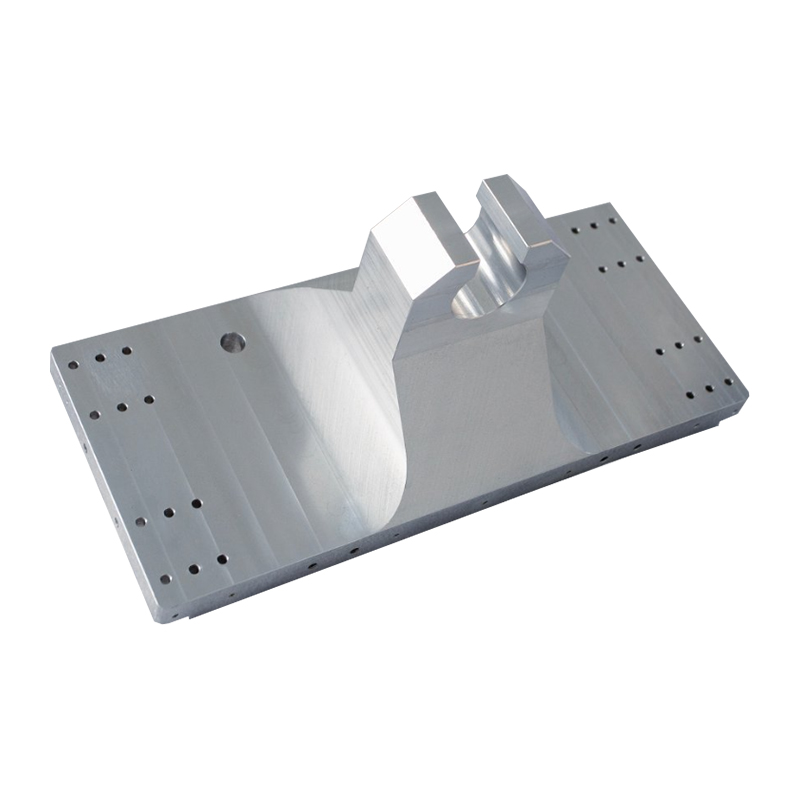
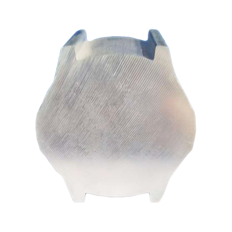
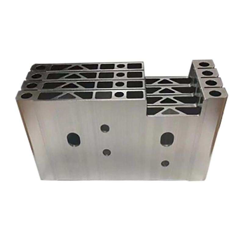
A large share of extruded profiles are not finished parts on their own; they require end-milling, drilling, tapping, or CNC cutting to length after leaving the press. This secondary machining introduces its own considerations that are easy to overlook if the extrusion and machining stages are planned separately rather than as one workflow. Profiles that will be end-machined benefit from being extruded slightly oversized in critical areas, since the as-extruded surface can carry minor die lines or oxide scale that machining then removes to reach final dimension.
Fixturing Thin-Walled Extrusions
Thin-walled hollow profiles are prone to deforming under clamping pressure during machining, which can cause a hole or slot to be cut slightly out of round once the part springs back after the fixture is released. Using internal mandrels or supports inside the hollow section during machining, rather than relying on external clamping force alone, keeps the wall from flexing and preserves roundness in bored features.
Common Quality Checkpoints Before Shipment
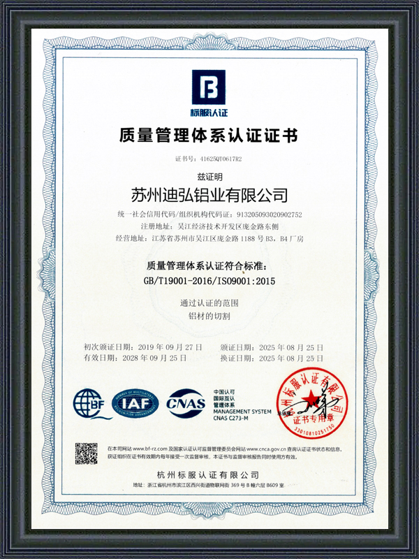
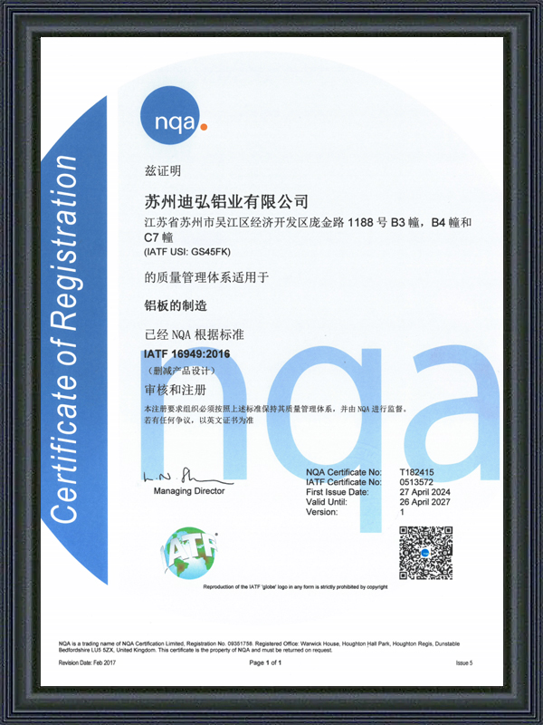
Consistent output across large production batches depends on inspection checkpoints placed at specific stages rather than a single inspection at the end of the line. Checking extrusion straightness and die correction accuracy right after the stretching stage catches problems before a batch is cut, packed, and shipped with a systemic defect. Sampling hardness after aging heat treatment confirms the alloy reached its intended temper, since visual inspection alone cannot detect an under-aged or over-aged batch. For machined parts, first-article inspection against the GD&T callouts on the drawing, rather than just the linear dimensions, catches assembly problems that a caliper check would miss entirely.


 English
 Español
 عربى
عربى